8259 Interrupt Controller
![]()
![]()
![]()
What are Interrupts?
There are two methods to send data from external devices to CPU. One method is called polling. In this method, we check the data ports of the device in certain intervals to see if some thing is there. If there is some data in the port, the system fetch it and store it. The problem with this method is that the system has to waste a lot of clock-cycles to check the port. Another problem is that there is a small chance that the system might miss the data when it is not checking the port. So this method is not practical because of the fact that the clock-cycles the system wasting, could be used to do other useful functions like task switching and memory management modules. The second method is through the method of interrupt mechanism. In this method, the the device that wants to send data gets the attention of the CPU by interrupting the CPU. The CPU finishes currently executing instruction and calls the system module called Interrupt Handler (Service Routine) to service the interrupt. The interrupt handler fetches the data and store it. This way the only time it is necessary to use clock-cycles is when there is an interruption needed to fetch data from the device.
2. How does it work?
All 80x86 processors uses 8259 family of micro-chips (Programmable Interrupt Controller [PIC]) to do the job of controlling the interrupts. This chip acts as a mediator between the device and the CPU. One PIC has 8 IRQ lines and there are two PICs in a normal PC. That means we have a total of 16 IRQ lines. This also means we can have as much as 16 external devices. Not exactly. In a PC, the second PIC is connected to the first one as a slave. And usually, the slave is connected to the master in the masters second IRQ line.
When the interrupt occurs, the chip interrupts the CPU. All 8259 controllers have 3 registers inbuilt and 1 controller unit called Priority Resolver. The three register are called IMR (Interrupt Mask Register), IRR (Interrupt Request Register), ISR (In Service Register).
|
Interrupt Mask Register |
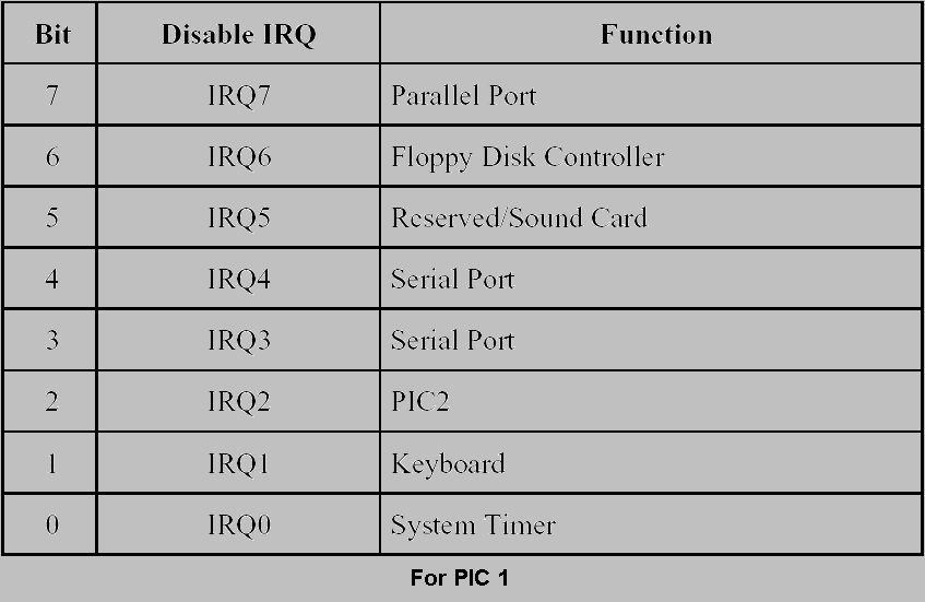
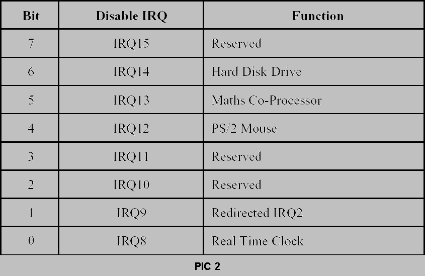
When an interrupt occurs, the controller checks if that interrupt have been masked by the system. The mask byte is stored in this register. Each bit in the register corresponds to an IRQ line. Below is the table that shows the bits of all IRQ line in both PICs. The table also gives a short description on what the IRQ line is for. If the interrupt is not masked it goes to the next stage.
|
Interrupt Request Register |
If an interrupt is not masked, they will register their request in this register by setting the appropriate bit in the register. Now if more than one interrupt is requesting service, this register holds all requests until all of them have been processed appropriately. If there is more than one interrupts, the Priority Resolver sorts the interrupt according the priority of the interrupt. For example IRQ 0 has priority over IRQ 1.
|
Interrupt Service Register |
Now the controller knows which interrupt to process, it interrupts the processor through the by sending a INT pulse to the INT pin on the processor. After finishing it's current instruction, processor acknowledges the 8259 controller by sending an INTA pulse back. After receiving the INTA pulse, the controller store the interrupt in ISR and resets the bit in IRR.
The processor sends another INTA pulse to the 8259 controller asking it to place a 8-bit pointer on the data bus. This pointer corresponds to the entry in the IDTR. Then, the processor switches the code pointed by the interrupt gate (task gate or call gate) in the IDT. From there it goes like any other far calls. Now, there is a little difference. During a normal far-call, the processor pushes CS and EIP on to the stack and RET pops them of the stack. In the case of an interrupt, the processor pushes CS, IP and EFLAGS onto the stack. The interrupt handler should use instruction IRET instead of RET to end the interrupt module. For example it should be like the sample below:
IT_Handler:
pushad
...............
popad
IRET
Once you are finished processing the interrupt, you need to send End Of Interrupt (EOI) command to the controller. Upon receiving this command, the controller resets the In-Service Register.
3. How do we initialize the Controller?
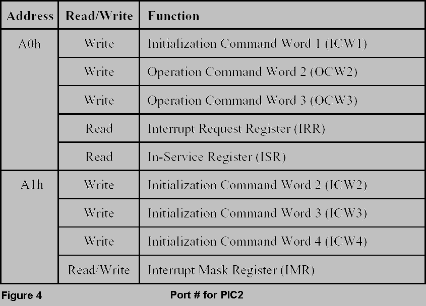
To initialize the controller, you need to send Initialization Command Words (ICW) to the controller. These commands words [2-bytes] depending on the order they are send has different functions. There are 4 initialization command words that are used to initialize the controller. There are also the so called Operational Command Words (OCW). They can be send to the controller in any order but each has it's own meaning. The way you access these PIC devices is through ports. Each of these controllers have 2 ports to send and receive commands. For PIC1 there are two ports; 20H and 21H. For PIC2 the ports are A0H and A1H. Certain commands can only send to certain ports. That means you cannot send Initialization Command Word 3 to 20H. In Figure 3 and 4 you will see what goes to what.

To initialize the controller you need to send Initialization Command Words. Below you will find a table that describes each bits of the commands. Also, you will see sample code that initializes the controller. That is the code straight from my system. Figure 5 through 8 talks about ICW and Figure 9 through 11 talks about OCW.
![]()
![]()
![]()